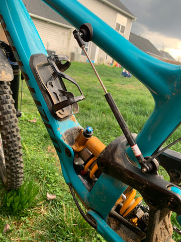
This will be an evolving thread on examples of how to mount the rear sensor. We are constantly improving our mounting options. Most of the parts will be available for purchase and may be in prototype form when the picture was taken. If you want any bracket you see that is 3D printed, we can either have one made for you, or you can get the file from us and print it yourself if you have a printer.

For shocks that the minimum closing distance of the sensor is greater than the eye to eye of the shock, you need an extender bracket to make sure the sensor doesn't get damaged when you hit bottom. Our software prevents this from happening by throwing a calibration error. If you see this error, it's because you short stroked the sensor when mounting.
Yep, it can measure this too. This mounting was a good approximation of what's happening. If you wanted it perfect, we'd have to write a bit of software, but for balancing a bike, this will suffice. 3M VHB tape adhering generic M5 bolt mounts to the top and bottom of fork.

We have circular flat mounts. These are threaded M3 x 6mm and are great for 9.4mm diameter body MIPS sensors. A slight curve is fine, but steeper radius surfaces need rounded surface mounts.

We have a 31mm diameter curved circular mount that's great for mounting to piggy back shocks. This one is an M4x6mm threaded post which is great for a ball joint mount. This standard ball joint mount is bolted to a body clamp for our 9.4mm diameter MIPS sensors. This provides lots of compliance while maintaining accuracy when measuring. This will get you out of a lot of difficult situations. And, you won't have to worry if you mounted your heim joint posts too short for the stroke of your shock. If you get an error, just loosen the body clamp and open up the sensor a little more. Try again until the error goes away.
For this Factory Yeti pilot, Dillon Santos, we used a lower DH Pro mounting post that typically installs on a 40mm DH Fork. The body of the Fox FloatX2 shock is 48mm diameter. It's a little tight, but with some 3M VHB tape, it's not going anywhere. Make sure to clean the surface with 50/50 water & rubbing alcohol. On the front of the MIPS sensor, we used our body clamp and pop joint. Lots of compliance. No complaints on this mount.
Yep, it's coming. Our software doesn't know the difference between a bicycle or a motorcycle. Both have telescoping forks, and a leverage curve on the rear. For this top AFM racer, Corey Call, the data showed him his fork was under-sprung by about 15%. He swapped to stiffer fork springs and he's now pushing further into the corner under braking. He's a smoking fast rider.
And another. We could have solved this with our pop joint body mount too. This is one way to do it if you are handy machining your own parts. But now we can use our pop joint body mount on the piggyback.

Here's our clever shock piggyback pop joint on an Evil Insurgent.

For coil shocks, we have a 2" stainless steel collar that is great for using with our pop joint. Just leave the mounting hardware on and it's easy to swap between bikes.

Here's our shock collar on a Push ElevenSix.

Just snap in the sensor when you want to test.

Here's our M4 Pop Joint post. Easy to stick on flat surfaces.
Here's a method using our Enduro Fork flexure and MI Air cap to the shock piggyback shraeder valve.


The suspension manufacturers may not like this method since they've gone to great care to hide this valve. But it provides a really tidy method to mount our MIPS sensor.

Above, we have a new method to mount on the 2020 Enduro or Demo. We are measuring the main link rotation angle. We have an angle/axle displacement curve in the bike file provided by Specialized engineering. The mounts are stick on with 3M VHB tape. This method also works for the Santa Cruz V10 and Megatower. These low tunnel shock designs are tough to mount a linear position sensor to. We've done it (see further above on Paul Serra's Enduro), but it wasn't fun and we can't imagine pushing this onto our customers. We're grateful for the support from Specialized and Santa Cruz to make this data available.
The coil kit works quite well on this Norco Aurum. Looks cool too.
Examples of what not to do...
On this Trek Slash, the transceiver box was mounted on the top tube, while the sensor body was mounted to the upper shock. As the shock compresses, the cable will stretch... unit no longer can. This is the result. Unfortunately this resulted in a complete replacement of the position sensor (Transceiver is fine). For this mount, the transceiver could be mounted on the shock piggyback reservoir or the rocker arm by the trunnion. Visualize the entire range of motion when mounting your sensor to avoid pitfalls like this.

Here's a Santa Cruz Megatower using the scalene method (angle of the main upper rotating link). Doesn't matter how you mount it, the app will ask you to take a couple of measurements, then the app will calculate the angle of the link and translate that to the rear axle position. The mounts in this pic are designed by us and they are available. Just ask.


